PART NUMBERS:
BA 602-8
BA 602-12
BA 602-16
BA 603-8
BA 603-12
BA 603-16

Innovative Engineering and Design
- Engineered for Maximum Efficiency for High Wind Zones and Uplift Locations
- Standard Clip Installation -No Special Tools or Instructions Required
- More Wind Uplift Capacity with Fewer Clips- reduced possibility for additional purlins/joists and costs associated with added steel
- Flexible Clip Placement to Control Wind Uplift and Corner/Edge Zones as requred
- Addresses Thermal Cycle Expansion when used in conjunction with High-Capacity Starter/Rake Plates with up to 7” of Travel -most expansion obtainable
- Excellent for ultra-long panel runs up to 500’-0” eliminates mid-slope roof fixity
- No Expensive Mid-slope Rafter Step Downs or Expansion Joints - panels fixed at eave
- Reduced Labor Costs Due to Fewer Clips Being Installed
- Two (2) Field seaming Options: TripleLok® or QuadLok®
- Achieves Highest Wind Uplift Values
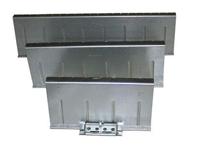
- Three (3) Different Clip Lengths 8”, 12”, and 16” -available for challenging zonal/code/engineering design requirements
- Different Clip Lengths Provide Increasing Levels of Uplift Capacity- See load tables
- Galvanized G-90 Material for Longevity/Durability
- Precision Stamped Parts Adhere to Strict Design Performance Tolerances
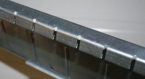
- No Need for Seam Clamps – clips outperform other systems using seam clamps(roof warts) not aesthetically pleasing
- Patented Engineered “Fingers” across Top of Clip Tab -eases seaming and increases side lap capacity after panels are seamed
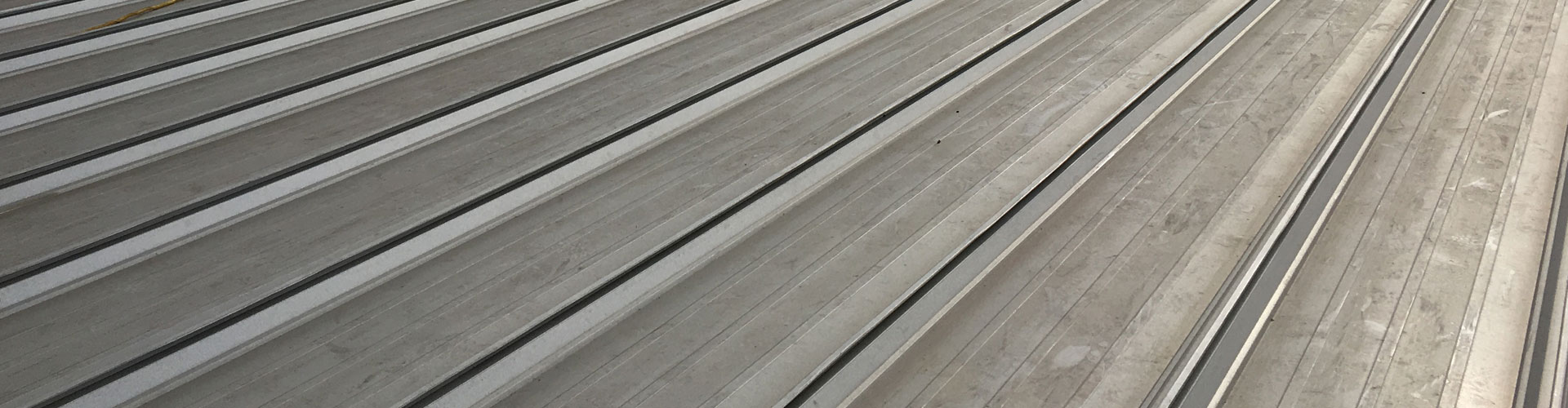
Best Solution for High Wind Zones
Typical solutions for high wind zones has been to add more purlins and clips or using seam clamps. These solutions not only increase cost and labor, seam clamps are not aesthetically pleasing.
The BRS WindClip is the best solution for High Wind Zones. The WindClip series comes in 3 different lengths to provide increasing levels of uplift capacity (see load tables).
The WindClip also allows for greater expansion and contraction making it possible to fix the roof system at eave for longer panel runs without using an (expensive) expansion joint or fixing the roof system in the middle.
“TS-324” Allowable Wind Uplift Loads - All Loads in Pounds per Square Foot
24 Gauge Material (Fy = 50 ksi) with BA-602-8 or BA-603-8 Clip and BRS Compliant Seamer
TripleLok Seam
| SPAN | 1592 TEST ULTIMATE LOAD | 1592 DESIGN LOAD | COE DESIGN LOAD |
| 2.0 | 180.5 | 106.0 | 109.4 |
| 2.5 | 97.0 | 100.1 | |
| 3.0 | 86.4 | 89.1 | |
| 3.5 | 74.1 | 76.4 | |
| 4.0 | 64.8 | 66.8 | |
| 4.5 | 57.6 | 59.4 | |
| 5.0 | 88.4 | 51.9 | 53.6 |
QuadLok Seam
| SPAN | 1592 TEST ULTIMATE LOAD | 1592 DESIGN LOAD | COE DESIGN LOAD |
| 2.0 | 246.7 | 144.8 | 149.5 |
| 2.5 | 132.2 | 136.4 | |
| 3.0 | 114.4 | 118.0 | |
| 3.5 | 98.1 | 101.2 | |
| 4.0 | 85.8 | 88.5 | |
| 4.5 | 76.3 | 78.7 | |
| 5.0 | 117.0 | 68.7 | 70.9 |
24 Gauge Material (Fy = 50 ksi) with BA-602-12 or BA-603-12 Clip and BRS Compliant Seamer
TripleLok Seam
| SPAN | 1592 TEST ULTIMATE LOAD | 1592 DESIGN LOAD | COE DESIGN LOAD |
| 2.0 | 217.6 | 127.8 | 131.9 |
| 2.5 | 116.8 | 120.5 | |
| 3.0 | 102.6 | 105.8 | |
| 3.5 | 87.9 | 90.7 | |
| 4.0 | 76.9 | 79.3 | |
| 4.5 | 68.4 | 70.6 | |
| 5.0 | 105.0 | 61.5 | 63.6 |
QuadLok Seam
| SPAN | 1592 TEST ULTIMATE LOAD | 1592 DESIGN LOAD | COE DESIGN LOAD |
| 2.0 | 312 | 183.3 | 189.1 |
| 2.5 | 166.8 | 172.1 | |
| 3.0 | 140.7 | 145.1 | |
| 3.5 | 120.6 | 124.4 | |
| 4.0 | 105.5 | 108.9 | |
| 4.5 | 93.8 | 96.8 | |
| 5.0 | 143.8 | 84.4 | 87.2 |
24 Gauge Material (Fy = 50 ksi) with BA-602-16 or BA-603-16 Clip and BRS Compliant Seamer
TripleLok Seam
| SPAN | 1592 TEST ULTIMATE LOAD | 1592 DESIGN LOAD | COE DESIGN LOAD |
| 2.0 | 254.8 | 149.7 | 154.4 |
| 2.5 | 136.6 | 140.9 | |
| 3.0 | 118.7 | 122.4 | |
| 3.5 | 101.7 | 104.9 | |
| 4.0 | 89.0 | 91.8 | |
| 4.5 | 79.1 | 81.6 | |
| 5.0 | 121.7 | 71.2 | 73.8 |
Notes:
1. The above tabulated loads are generated from certified ASTM E-1592 testing using BRS’s WindClips and BRS Compliant seamers. These design loads are not valid with other clips or seamers.
2. Intermediate design loads are interpolated from ultimate test loads.
3. Design loads contain safety factors calculated per AISI.
4. COE design load contains a 1.65 safety factor per COE 07416 Specification.
5. These load capacities are for the panel itself. Frames, purlins, clips, fasteners, and all supports must be designed to resist all loads imposed by the panel.
6. Allowable wind uplift loads have not been increased by 33% as allowed by some codes when wind load controls.
7. This material is subject to change with out notice. Contact Building Research Systems for most current values.